Introduction: Why PID Matters for Solar Cell Performance
A solar cell may deliver excellent efficiency during factory testing. However, high initial efficiency alone cannot guarantee reliable performance throughout a solar module’s operating life. Once manufacturers integrate cells with glass, encapsulants and other module components, the finished product must withstand electrical stress, heat, humidity and changing environmental conditions.
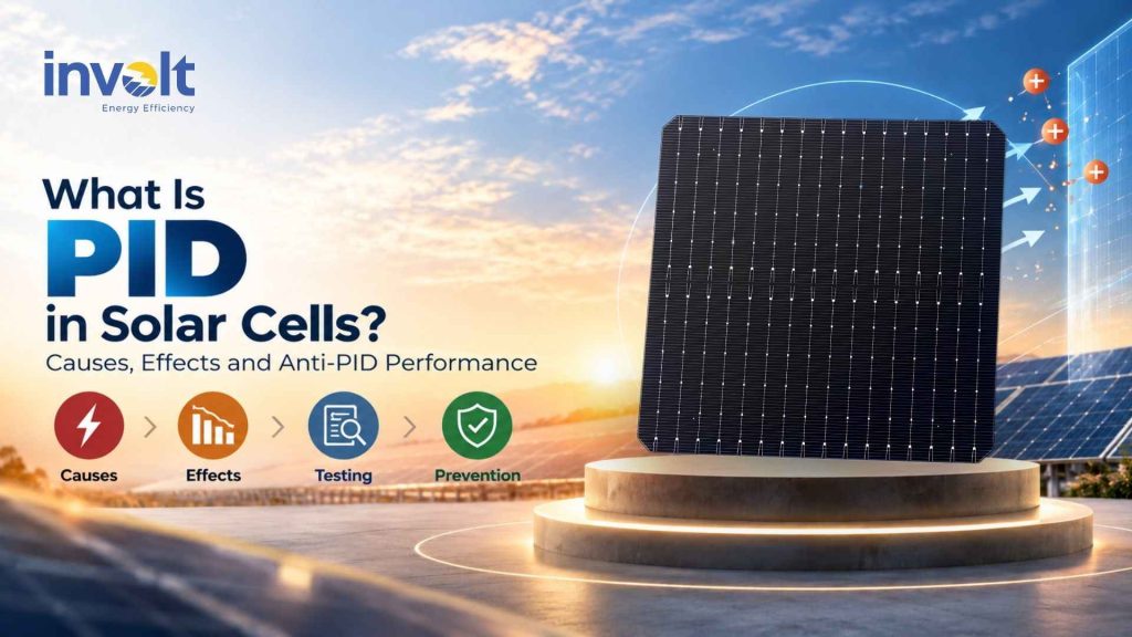
One important reliability concern is potential-induced degradation (PID). This phenomenon can reduce solar module power output when sustained voltage differences trigger unwanted electrical and material changes. The risk depends on cell technology, module construction and operating conditions.
For solar module manufacturers, understanding PID in solar cells is therefore essential. Selecting high-efficiency cells is only the starting point. Manufacturers must also consider PID-resistant cell design, material compatibility and module-level reliability testing.
As an N-Type TOPCon solar cell manufacturer in Gujarat, Involt Energy Pvt. Ltd. recognizes the importance of these considerations. Its G12R TOPCon cell design incorporates a PID-resistant SiOx + SiNx front coating, while final anti-PID performance requires qualification of the complete cell-and-module construction.
What Is PID in Solar Cells?
Potential-induced degradation (PID) is a form of solar module performance loss caused by electrical potential differences that drive unwanted leakage currents and changes in cell or module materials. Over time, these processes can reduce power output. The severity depends on the solar cell technology, module construction, environmental conditions and electrical system design.
Unlike ordinary ageing, PID involves specific electrical stress conditions. It can affect solar modules even when their cells initially meet the required efficiency and power specifications.
What Does PID Stand for in Solar Technology?
PID stands for Potential-Induced Degradation. In photovoltaic (PV) systems, the term describes degradation associated with sustained electrical potential differences between solar cells and other parts of the module or its surroundings.
A solar module contains interconnected cells, encapsulation materials, protective glass and other components. During operation, the cells may sit at a substantial voltage relative to the module frame or ground. This electrical stress can create leakage pathways through the module materials.
However, not every module responds in the same way. Cell architecture, protective coatings, encapsulant properties and operating conditions all influence PID susceptibility.
How Does Potential-Induced Degradation Occur?
PID develops when electrical stress drives processes that interfere with normal solar cell operation.
For example, in some crystalline-silicon modules, voltage stress can encourage mobile ions, including sodium from certain glass compositions, to migrate toward sensitive regions of the solar cell. Under susceptible conditions, these changes may create unwanted current pathways and reduce shunt resistance.
Other cell structures can experience PID-polarization, where charge accumulation affects surface passivation and increases electrical recombination. As a result, the cell converts less incoming sunlight into usable electrical power.
High temperature and humidity can accelerate certain PID mechanisms by influencing material conductivity and leakage currents. However, voltage polarity, cell structure and module materials determine which degradation process may occur.
The key distinction is that PID resistance depends on more than the solar cell alone. Manufacturers must evaluate how the cell behaves within the complete module construction under relevant electrical and environmental stress.
What Causes PID in Solar Cells and PV Modules?
Potential-induced degradation does not result from a single manufacturing defect. Instead, it develops when electrical stress interacts with susceptible solar cell structures and module materials. Voltage polarity, leakage pathways, glass composition, encapsulation and environmental conditions all influence the risk.
Understanding these factors helps solar module manufacturers select compatible materials and evaluate long-term reliability.
High Voltage Stress and Leakage Current
Solar cells in a connected PV string operate at different electrical potentials relative to ground. Consequently, some modules experience substantial voltage differences between their internal cell circuits and surrounding components, including the frame.
These differences create an electric field across the module’s insulating materials. If those materials permit leakage current, electrical charges or mobile ions can move through susceptible pathways.
Over time, these processes may disrupt cell operation and reduce power output. However, high system voltage alone does not guarantee PID. The outcome also depends on voltage polarity, insulation properties, cell architecture and environmental exposure.
Sodium Ion Migration and Solar Glass Composition
Many photovoltaic modules use soda-lime glass, which contains sodium. Under certain electrical and environmental conditions, sodium ions can migrate through the glass and adjacent materials toward the solar cell.
In susceptible crystalline-silicon cell structures, sodium-related changes can contribute to PID-shunting. This mechanism creates unwanted electrical pathways that allow current to bypass the intended circuit, reducing shunt resistance and potentially lowering module power.
However, sodium migration does not explain every form of PID. Other mechanisms involve charge accumulation and changes in surface passivation.
Therefore, manufacturers must assess the interaction between glass composition, cell coatings and encapsulation materials rather than assume that changing one component eliminates the risk.
Temperature, Humidity and Moisture Ingress
High temperature and humidity can accelerate PID by changing how electrical charges move through module materials.
Heat increases the mobility of certain ions. Meanwhile, humid conditions can increase surface conductivity and influence leakage-current pathways. Together, these factors may intensify electrical stress under susceptible operating conditions.
Moisture ingress can also affect encapsulation and insulation properties over time. However, PID does not require visible water damage or a failed module seal.
For module manufacturers supplying products to hot or humid regions, PID resistance deserves particular attention during material selection and reliability qualification.
Encapsulation Materials and Cell Surface Coatings
Encapsulation materials help protect solar cells, maintain electrical insulation and bond the module’s internal components. Their electrical properties also influence PID susceptibility.
For example, ethylene-vinyl acetate (EVA) and polyolefin elastomer (POE) can behave differently under electrical and environmental stress. Some POE-based constructions offer advantages for particular PID mechanisms, but the final outcome depends on the complete material combination.
Solar cell surface coatings matter as well. Anti-reflective and passivation layers influence electrical behavior at sensitive cell interfaces. Their composition and properties can affect charge accumulation, ion-related degradation and recombination losses.
Involt Energy’s G12R N-Type TOPCon solar cell incorporates a SiOx + SiNx front coating with a PID-resistant design, according to its technical datasheet. Nevertheless, manufacturers must qualify anti-PID performance after integrating the cell into the intended module construction.
System Voltage, Grounding and String Configuration
A PV system’s electrical design influences the voltage stress that individual modules experience.
In 1,000 V and 1,500 V systems, modules at different string positions may operate at different potentials relative to ground. Depending on the inverter topology and grounding arrangement, particular modules can experience conditions that favor certain PID mechanisms.
Voltage polarity matters because different cell architectures respond differently to electrical stress. A configuration that reduces one degradation mechanism may not address another.
Some compatible inverter systems offer anti-PID functions or recovery modes. However, installers must follow the inverter manufacturer’s requirements and applicable electrical safety rules. They should never change grounding arrangements solely to address PID without confirming system compatibility.
For solar module manufacturers, the central lesson is clear: PID susceptibility reflects the interaction between cell design, module materials and operating conditions. A cell’s anti-PID features provide an important starting point, but reliable performance requires testing the final module configuration under relevant electrical stress.
What Are the Different Types of PID in Solar Cells?
Not all potential-induced degradation follows the same physical process. Two important mechanisms are PID-shunting (PID-s) and PID-polarization (PID-p). Both can reduce photovoltaic performance, but they affect different parts of the solar cell and produce different electrical changes.
For solar module manufacturers, this distinction matters. A material combination that resists one PID mechanism may still remain vulnerable to another. Therefore, manufacturers must evaluate the relevant degradation mechanisms when qualifying a new solar cell technology.
PID-Shunting (PID-s)
PID-shunting occurs when voltage-driven ion migration creates unwanted electrical pathways through a solar cell’s junction. These pathways allow current to bypass its intended route and reduce the cell’s shunt resistance.
Researchers have linked this mechanism to sodium ions that migrate from surrounding materials and accumulate along certain crystalline defects. Under susceptible conditions, these defects can develop into conductive pathways.
As shunt resistance decreases, the solar cell may lose fill factor and maximum power output. PID-shunting has received particular attention in conventional P-Type crystalline-silicon cell structures, although susceptibility depends on the specific design and materials.
Some affected cells can recover part of their performance under suitable conditions. However, recovery is not always complete, especially when the degradation involves persistent structural or material changes.
PID-Polarization (PID-p)
PID-polarization occurs when electrical stress changes the charge distribution within or near a solar cell’s dielectric passivation layers. These changes can weaken surface passivation and increase charge-carrier recombination.
Effective passivation helps solar cells retain the electrical charges they generate from sunlight. When polarization disrupts this protection, the cell can experience reductions in photocurrent, open-circuit voltage and power output.
This mechanism is especially relevant when evaluating modern N-Type TOPCon solar cells, which rely on carefully engineered passivation structures to achieve high conversion efficiency.
Unlike PID-shunting, PID-polarization does not necessarily create a conductive pathway through the cell junction. Instead, it alters the electrical conditions at sensitive interfaces.
Some polarization-related losses can recover when conditions change, including during suitable light exposure or electrical-bias recovery procedures. Nevertheless, recovery depends on the cell architecture, stress history and underlying mechanism.
For a deeper understanding of these passivating structures, see Involt Energy’s article on What Is TOPCon Solar Cell Technology?
Other PID-Related Degradation Mechanisms
Researchers have also identified other forms of potential-induced degradation, including ion-related surface passivation damage, corrosion and degradation within module materials.
PID-penetration occurs when mobile ions reach sensitive silicon interfaces and impair surface passivation. Unlike classic PID-shunting, this mechanism may reduce photocurrent and voltage without primarily producing a low-resistance electrical shunt.
PID-corrosion involves electrochemical changes that can damage cell surfaces or other susceptible materials. Depending on the affected structure and severity, such damage may be difficult to reverse.
Certain high-voltage conditions can also contribute to deterioration within the surrounding module construction. However, manufacturers should distinguish these material failures from cell-level PID mechanisms rather than group every voltage-related defect under one explanation.
PID-Shunting vs PID-Polarization: Key Differences
1. PID-Shunting (PID-s)
- Mechanism: Ion-related conductive pathways increase electrical leakage through susceptible cell structures.
- Performance impact: Lower shunt resistance can reduce fill factor and maximum power output.
- Recovery: Partial recovery may occur under suitable conditions. However, persistent damage can limit recovery.
2. PID-Polarization (PID-p)
- Mechanism: Electrical stress changes charge distribution near sensitive passivation layers.
- Performance impact: Increased surface recombination can reduce current, voltage and power output.
- Recovery: Some polarization-related losses can recover, depending on the cell architecture and recovery conditions.
3. PID-Penetration
- Mechanism: Mobile ions reach sensitive silicon interfaces and interfere with surface passivation.
- Performance impact: Increased recombination can reduce photocurrent, voltage and power.
- Recovery: Recovery depends on the extent and nature of the material changes.
4. PID-Corrosion (PID-c)
- Mechanism: Electrochemical reactions damage susceptible cell or module materials.
- Performance impact: Material deterioration can reduce electrical performance and long-term reliability.
- Recovery: Permanent material damage may limit or prevent recovery.
What should solar module manufacturers take away?
A general anti-PID claim does not explain which degradation mechanisms a cell or module design can resist. Buyers should examine the test conditions, voltage polarity, affected module face and measured electrical changes before comparing reliability claims.
This is particularly important when selecting N-Type TOPCon cells for new module designs. Strong cell-level passivation and PID-resistant coatings support reliability-focused engineering, but the final module construction still determines how the complete product responds to high-voltage stress.
How Does PID Affect Solar Panel Performance?
Potential-induced degradation (PID) can reduce the electrical performance of a photovoltaic module even when its solar cells initially meet their factory specifications. The impact depends on the degradation mechanism, voltage stress, operating conditions and module construction.
For solar module manufacturers, the concern extends beyond an immediate power reduction. PID can also affect performance consistency, energy yield and long-term reliability.
Power Output and Conversion Efficiency Loss
PID can reduce a solar module’s maximum power output by increasing electrical losses within its cells. As these losses grow, the module delivers less usable electricity under comparable operating conditions.
In PID-shunting, unwanted current pathways reduce the electrical power available at the module terminals. In PID-polarization, changes in surface passivation increase charge-carrier recombination and can reduce the current or voltage that a cell produces.
Both mechanisms can lower maximum power (Pmax), although they affect electrical parameters differently.
Illustrative example — not an Involt test result
Consider a hypothetical 600 W solar module:
- Initial maximum power: 600 W
- Maximum power after hypothetical PID-related loss: 570 W
- Power reduction: 30 W, or 5%
This example simply demonstrates the calculation. It does not represent a typical PID loss, an industry benchmark or a measured result for Involt Energy’s solar cells.
Actual performance changes require controlled testing and a comparison against the module’s initial electrical characteristics.
Fill Factor, Shunt Resistance and Electrical Parameters
PID does not always affect every electrical parameter equally. The pattern depends on the underlying mechanism.
Fill factor (FF) describes how effectively a solar cell delivers power relative to the product of its open-circuit voltage (Voc) and short-circuit current (Isc). When PID introduces additional electrical losses, fill factor may decrease.
Shunt resistance (Rsh) indicates how strongly a solar cell resists unwanted current leakage. PID-shunting can lower this resistance, allowing more current to bypass the intended electrical path.
Meanwhile, PID-polarization can increase surface recombination. Depending on the cell architecture and severity, this may affect Voc, Isc and maximum power.
These differences matter during reliability evaluation. A decline in maximum power alone cannot identify the PID mechanism. Engineers must examine the complete current–voltage (I–V) curve and supporting diagnostic evidence.
For further background on cell-level electrical characteristics, see Involt Energy’s TOPCon Solar Cell Specifications: B2B Buyer’s Guide.
Long-Term Energy Yield and Module Reliability
A module’s initial power rating represents only one part of its performance profile. Over its operating life, the module must continue converting sunlight into electricity under changing temperatures, humidity levels and electrical stress.
When PID reduces power output, the affected module may generate less energy than an otherwise comparable module operating under similar conditions. The resulting energy-yield impact depends on when degradation develops, how severe it becomes and whether recovery occurs.
PID can also create uneven performance across a PV string because individual modules may experience different electrical potentials relative to ground.
For solar module manufacturers, this creates an important qualification challenge. They must evaluate not only initial cell efficiency but also the compatibility of the selected cells with the intended glass, encapsulation, module structure and electrical operating conditions.
The practical takeaway: High-efficiency solar cells provide a strong starting point, but their integration into a properly qualified module determines how the finished product responds to PID-related stress. Cell-level design and module-level reliability testing must work together.
How Can Manufacturers Detect and Test PID?
Manufacturers detect potential-induced degradation (PID) by comparing a photovoltaic module’s electrical performance before and after controlled voltage stress. Current–voltage (I–V) measurements reveal performance changes, while electroluminescence (EL) imaging helps identify affected cells. Standardized testing then evaluates how a specific module construction responds to PID-related stress.
For solar module manufacturers sourcing N-Type TOPCon cells, these evaluations serve an important purpose: they help determine whether the selected solar cells, glass, encapsulants and other materials work together reliably.
A solar cell’s PID-resistant design offers a valuable starting point. However, only testing the intended module construction can establish its response under the specified test conditions.
I–V Curve Analysis and Electrical Performance Testing
An I–V curve shows how a photovoltaic module’s current changes as its operating voltage varies. Engineers use this curve to evaluate electrical performance and identify changes after reliability testing.
For a closer look at the electrical parameters that matter during cell selection, explore Involt Energy’s TOPCon Solar Cell Specifications: B2B Buyer’s Guide
During PID assessment, manufacturers compare measurements taken before and after electrical stress. Important parameters include:
- Maximum power (Pmax): Shows whether the module delivers less electrical power after testing.
- Open-circuit voltage (Voc): Helps identify voltage-related performance changes.
- Short-circuit current (Isc): Reveals changes in current-generating capability.
- Fill factor (FF): Indicates how effectively the module delivers power near its maximum power point.
- Shunt resistance (Rsh): Provides diagnostic insight into unwanted leakage pathways, particularly for PID-shunting.
Different PID mechanisms produce different electrical signatures. For example, PID-shunting can reduce shunt resistance and fill factor. PID-polarization may instead affect current and voltage through changes in surface passivation.
Therefore, engineers should examine the complete I–V curve rather than rely on a single electrical parameter.
They must also control measurement conditions. Temperature, irradiance and stabilization history can influence results independently of PID.
Electroluminescence Imaging and Diagnostic Limitations
Electroluminescence (EL) imaging helps engineers identify electrical irregularities within interconnected solar cells. During inspection, an external power source drives current through the module, and a suitable camera captures the light emitted by its cells.
The resulting image can reveal nonuniform electrical behavior that ordinary visual inspection may miss.
Depending on the PID mechanism and imaging conditions, affected regions may appear darker than surrounding areas. Engineers can compare EL images taken before and after voltage-stress testing to investigate changes.
However, a dark region in an EL image does not automatically prove PID.
Cell cracks, interconnection defects, recombination-related losses and other electrical problems can also influence EL appearance. Furthermore, imaging current and measurement conditions affect the patterns that engineers observe.
For reliable diagnosis, manufacturers should interpret EL images alongside I–V measurements, test history and other relevant evidence.
This combined approach helps distinguish suspected PID from unrelated manufacturing or handling defects.
IEC TS 62804-1 and PID Resistance Qualification
IEC TS 62804-1:2025, Edition 2.0, provides test methods for detecting potential-induced degradation in crystalline-silicon photovoltaic modules.
The International Electrotechnical Commission published this edition in June 2025. It addresses different PID mechanisms rather than treating all voltage-related degradation as one phenomenon.
The specification includes three principal testing approaches:
1. PID-shunting assessment
These procedures apply high-voltage stress under defined laboratory conditions, primarily in the dark. They help evaluate degradation associated with unwanted electrical pathways.
2. PID-polarization assessment
These procedures incorporate ultraviolet irradiation during voltage stress. This distinction matters because illumination can influence polarization-related behavior in cells with dielectric passivation layers.
3. PID-polarization recovery assessment
A separate procedure evaluates recovery under ultraviolet exposure after relevant stress testing.
The standard’s scope and test conditions matter particularly for modern passivated cell architectures, including N-Type TOPCon.
However, IEC TS 62804-1 is a technical specification for module-level PID assessment, not proof that every tested product will remain unaffected by PID throughout its operating life.
Manufacturers must interpret results in relation to the exact cell technology, module materials, voltage polarity, test conditions and intended application.
What Should a PID Test Report Include?
A useful PID test report should do more than state that a module passed or failed.
For technical evaluation and supplier qualification, solar module manufacturers should examine the following information:
1. Cell and module identification
The report should identify the tested module design, cell technology, material configuration and relevant production details. This helps buyers determine whether the results apply to their intended construction.
2. Test standard and edition
The documentation should specify the applicable test method, including IEC TS 62804-1:2025 when that edition was used.
3. Electrical stress conditions
Buyers should review the applied voltage, polarity, duration, temperature, humidity and illumination conditions, as relevant to the test procedure.
4. Electrical measurements
The report should document the required pre-stress and post-stress measurements, including changes in maximum power and other relevant electrical parameters.
5. Diagnostic evidence
EL images and additional measurements, where available, can help engineers investigate the nature and distribution of degradation.
6. Recovery results
If the laboratory performed recovery testing, the report should distinguish performance immediately after stress from performance measured after recovery.
7. Results, acceptance criteria and deviations
The report should state the observed changes, applicable evaluation criteria and any departures from the prescribed procedure. Buyers should avoid interpreting an unexplained ‘anti-PID’ label as a complete qualification record.
Laboratory PID Qualification vs Real-World Performance
Laboratory PID testing evaluates a module’s response to defined stress conditions. It does not directly predict its exact power loss or service life in every installation.
In the field, modules experience changing temperatures, humidity, sunlight and electrical potentials. Their operating history can also influence degradation and recovery.
Consequently, two module designs that perform similarly in one laboratory test may behave differently under other operating conditions.
For manufacturers integrating N-Type TOPCon solar cells, the practical approach is to combine standardized PID testing with broader module reliability qualification and appropriate field-performance monitoring.
The key takeaway: Cell-level PID-resistant features support reliability-focused product development, but module manufacturers must validate the finished construction. Clear test documentation provides stronger evidence than an unsupported anti-PID claim.
Can PID Be Reversed in Solar Cells?
Yes, some forms of potential-induced degradation (PID) can be partially or substantially reversed. However, recovery depends on the underlying degradation mechanism, cell architecture and extent of damage. Electrical-bias treatments or changes in operating conditions may restore performance in certain cases. In contrast, permanent electrochemical or material damage can limit recovery.
For solar module manufacturers, this distinction matters because recovering lost power does not necessarily eliminate the conditions that caused PID.
When Is PID Recovery Possible?
PID recovery becomes possible when the degradation involves electrical or ionic changes that can return toward their original state without leaving significant permanent damage.
For example, PID-polarization can alter charge distribution near a solar cell’s passivation layers. Under suitable conditions, changes in electrical bias or illumination may help restore the surface’s electrical behavior and reduce recombination losses.
Certain cases of PID-shunting may also show recovery when the processes responsible for unwanted current pathways can reverse. However, recovery rates and completeness vary.
Engineers must consider the specific cell structure, voltage polarity, temperature, illumination and duration of exposure. A recovery method that works for one photovoltaic technology may not work for another.
Importantly, a temporary increase in power after recovery does not prove that a module has achieved permanent PID resistance. The degradation may return if the original stress conditions persist.
How Do Anti-PID Recovery Devices Work?
Some photovoltaic systems use anti-PID recovery devices to reduce the effects of voltage-related degradation.
These devices typically operate through compatible inverter functions or dedicated electrical equipment. Depending on the system design, they apply a controlled electrical potential during suitable periods, often when the PV array is not generating power.
The objective is to counteract certain voltage-driven changes that contributed to degradation.
For example, a recovery system may encourage redistribution of mobile charges or ions under conditions that favor performance restoration. However, the appropriate voltage polarity and recovery procedure depend on the cell technology and PID mechanism.
Anti-PID recovery equipment is not a universal repair solution. It cannot reliably reverse every form of degradation, and an unsuitable electrical configuration may create additional safety or equipment risks.
System operators should therefore follow the inverter or recovery-device manufacturer’s instructions and verify compatibility with the PV array before enabling any recovery function.
When Can PID Damage Become Permanent?
PID-related performance loss may become difficult or impossible to reverse when electrical stress causes lasting changes in cell or module materials.
Examples include:
- Electrochemical corrosion: Chemical reactions may permanently damage conductive or sensitive material interfaces.
- Persistent structural defects: Certain ion-related changes can leave electrical leakage pathways that do not fully recover.
- Passivation damage: Severe or persistent changes at sensitive interfaces may prevent complete restoration of the original electrical performance.
- Secondary material deterioration: Damage to encapsulation or other module components can complicate recovery and affect long-term reliability.
The extent of recovery also depends on how early manufacturers or system operators identify the problem.
For this reason, prevention and qualification remain more dependable strategies than relying on recovery after degradation occurs.
Solar module manufacturers should select suitable cell and module materials, evaluate relevant PID mechanisms and conduct appropriate reliability testing before commercial production.
Key takeaway: Some PID mechanisms allow meaningful performance recovery, but others can cause lasting damage. For N-Type TOPCon solar cells, manufacturers must assess the relevant degradation mechanism and qualify the final module construction rather than assume that every anti-PID recovery method will work.
How Can PID Be Prevented or Reduced in Solar Modules?
Potential-induced degradation (PID) can be prevented or reduced through a combination of PID-resistant solar-cell design, suitable module materials, controlled electrical operating conditions and reliability testing. No single measure guarantees protection because PID depends on the interaction between the solar cells, module construction and PV system.
For solar module manufacturers, an effective prevention strategy begins with cell selection and continues through module qualification. System-level measures provide an additional layer of protection once the modules are installed.
PID-Resistant Cell Coatings and Surface Passivation
Cell-level prevention begins with controlling the electrical properties of the solar cell’s surfaces and interfaces.
Solar-cell manufacturers use dielectric coatings and passivation structures to reduce unwanted charge-carrier recombination and support stable electrical performance. Depending on their composition and design, these layers can also influence how a cell responds to voltage stress and mobile ions.
For N-Type TOPCon solar cells, surface passivation is particularly important because certain PID mechanisms can disturb the electrical conditions at sensitive interfaces.
Involt Energy’s G12R N-Type TOPCon solar cell incorporates a SiOx + SiNx front coating with a PID-resistant design, as specified in its technical datasheet. Its rear-side structure includes doped polysilicon and SiON + SiNx passivation layers.
These features are relevant to cell-level reliability engineering. However, a PID-resistant coating is a design characteristic—not proof that every module built with the cell will resist PID under all operating conditions.
Module manufacturers must still evaluate the cells within their intended module construction.
Suitable Encapsulation Materials and Module Construction
Module-level prevention focuses on limiting harmful leakage-current pathways and reducing the conditions that promote ion migration.
Solar cells operate inside a layered structure that includes glass, encapsulation materials, electrical interconnections and protective components. The properties of these materials influence how voltage stress, moisture and mobile ions interact with the cells.
Important considerations include:
- Encapsulant properties: Electrical resistivity, moisture-related behavior and compatibility with the selected cells can influence PID susceptibility.
- Solar glass composition: The availability and movement of mobile ions, including sodium, can contribute to certain PID mechanisms.
- Moisture protection: Suitable edge sealing and module construction help limit moisture ingress that may increase electrical leakage.
- Material interfaces: The interaction between glass, encapsulant and cell coatings can affect long-term electrical stability.
Encapsulation materials such as EVA and POE should not be judged by name alone. Their formulations, processing conditions and behavior within the complete module stack matter.
For example, selecting a material with favorable electrical properties does not automatically guarantee PID resistance if another part of the module construction creates a vulnerable leakage pathway.
The complete glass–encapsulant–cell–encapsulant–backsheet or glass stack must be qualified as a system.
Voltage Management and Compatible Inverter Functions
System-level mitigation aims to reduce the electrical conditions that can trigger or accelerate PID during operation.
PID susceptibility is influenced by the potential difference between solar cells and grounded parts of the module or installation. The magnitude and polarity of this voltage depend on the electrical architecture of the PV system.
System designers should therefore evaluate string configuration, grounding arrangements, inverter topology and the operating voltage range.
Depending on the equipment and system design, compatible inverter functions may help manage PID-related voltage stress. Some systems also support dedicated anti-PID functions intended to reduce degradation or assist recovery.
However, these features must be evaluated for the specific cell technology and module design. A voltage strategy that reduces one PID mechanism may not provide the same benefit for another.
Grounding or changing voltage polarity should never be treated as a universal PID remedy. Any electrical configuration must comply with applicable safety requirements and the instructions of the module and inverter manufacturers.
For module manufacturers, the practical objective is to understand the expected system conditions and ensure that product qualification reflects relevant electrical stresses.
Reliability Testing and Quality Control
Reliability testing connects cell-level prevention and module-level design with measurable evidence.
Manufacturers should evaluate PID susceptibility during product development, especially when introducing a new cell technology, encapsulant formulation, glass supplier or module construction.
A practical quality-control approach includes:
- Incoming cell verification: Confirm the supplied cell design, electrical characteristics and relevant technical documentation.
- Material compatibility checks: Evaluate how the selected encapsulants, glass and cell surfaces interact.
- Module-level PID testing: Assess the finished module construction using applicable procedures, including IEC TS 62804-1:2025 where relevant.
- Electrical and imaging diagnostics: Compare I–V measurements and supporting electroluminescence images before and after testing.
- Change control: Reassess reliability when significant materials, processes or construction details change.
Testing should address the PID mechanisms relevant to the selected cell technology. A result obtained for one module design should not automatically be applied to a different material stack.
For manufacturers sourcing N-Type TOPCon solar cells, supplier documentation is an important input, but it cannot replace qualification of the finished module.
The key takeaway: PID prevention requires three connected levels of engineering. Solar-cell manufacturers develop PID-resistant cell structures. Module manufacturers select compatible materials and validate the complete construction. PV system designers and operators manage electrical conditions that can influence degradation in the field.
When these responsibilities are addressed together, manufacturers can make more informed reliability decisions without relying on unsupported claims of complete PID immunity.
Are N-Type TOPCon Solar Cells Resistant to PID?
N-Type TOPCon solar cells can be engineered for improved resistance to potential-induced degradation (PID), but they are not inherently immune to it. Their response to voltage stress depends on surface passivation, dielectric coatings, cell polarity and the materials used in the finished module.
For solar module manufacturers, the important question is not whether TOPCon technology is universally PID-resistant. It is whether a specific TOPCon cell design performs reliably within the intended module construction under relevant test conditions.
How TOPCon Cell Architecture Influences PID Susceptibility
TOPCon stands for Tunnel Oxide Passivated Contact. The technology uses an ultrathin tunnel oxide and a doped polysilicon contact structure to reduce charge-carrier recombination while allowing selective carrier transport.
This passivated-contact architecture supports high conversion efficiency, but it does not eliminate every possible PID mechanism.
In particular, the electrical behavior of dielectric passivation layers matters. Under certain voltage-stress conditions, charge accumulation or redistribution near sensitive interfaces can disturb surface passivation.
This phenomenon is associated with PID-polarization (PID-p).
When polarization affects passivation, surface recombination can increase. Depending on the cell design and operating conditions, the result may be reduced current, voltage or maximum power.
Other degradation pathways, including ion-related effects and electrochemical damage, may also be relevant under particular conditions.
For this reason, engineers must assess more than the TOPCon contact structure alone. Front-side coatings, rear-side passivation, voltage polarity and interactions with module materials can all influence the observed response.
The distinction matters: TOPCon passivation helps improve normal cell performance, but the stability of that passivation under PID stress must be verified separately.
PID in N-Type vs P-Type Solar Cells
N-Type and P-Type solar cells differ in their base doping, contact structures and typical passivation designs. These differences can influence which PID mechanisms become important and how they affect electrical performance.
However, the conductivity type alone does not determine PID resistance.
In some conventional P-Type crystalline-silicon cell designs, PID-shunting has been a significant concern. Under suitable voltage and environmental conditions, ion-related effects can create unwanted electrical pathways, reducing shunt resistance and fill factor.
N-Type cells may exhibit different responses because their junction configurations and passivated interfaces differ. In certain N-Type architectures, PID-polarization can become an important degradation mechanism.
That does not mean every P-Type cell develops PID-shunting or every N-Type cell develops PID-polarization. Actual behavior depends on the complete cell architecture, coatings, voltage polarity and module materials.
Recovery behavior can also differ. Some polarization-related effects may be reversible under appropriate conditions, while other degradation processes can leave lasting damage.
For module manufacturers comparing N-Type and P-Type technologies, PID performance should be assessed through technology-specific testing rather than broad claims that one doping type is always safer.
TOPCon vs PERC: Why Technology Alone Cannot Guarantee PID Resistance
TOPCon and PERC use different approaches to surface passivation and electrical contact formation.
PERC (Passivated Emitter and Rear Cell) technology uses rear-side passivation with localized electrical contacts. TOPCon uses a passivated-contact structure incorporating tunnel oxide and doped polysilicon.
These architectural differences influence carrier recombination, electrical performance and potential responses to PID stress.
However, comparing the technologies only by their names can be misleading.
A TOPCon cell with an unsuitable coating or poorly matched module materials may experience PID-related performance loss. Likewise, a properly engineered and qualified PERC module may demonstrate satisfactory PID resistance under its specified test conditions.
The outcome depends on factors such as:
- Cell surface and contact design: The stability of passivation layers and interfaces under electrical stress.
- Voltage polarity: The direction of the electrical potential relative to grounded module components.
- Glass and encapsulation: Material properties that influence leakage current and mobile-ion behavior.
- Module construction: The complete combination of cells, interconnections and protective materials.
- Qualification conditions: The test method used and the PID mechanisms it evaluates.
For buyers, the most useful comparison is therefore between specific, documented cell-and-module designs, not generic TOPCon and PERC labels.
This is particularly important when reviewing anti-PID claims. A high initial cell efficiency, advanced passivation architecture or PID-resistant coating does not independently establish the long-term PID performance of the finished module.
The key takeaway: N-Type TOPCon offers an advanced passivated-contact architecture, but PID resistance remains a design and qualification question. Solar module manufacturers should examine the selected cell’s coating structure, the intended module materials and relevant test evidence before making reliability claims.
Anti-PID Design in Involt Energy’s G12R N-Type TOPCon Solar Cells
For solar module manufacturers, PID resistance begins with the solar cell’s design but must be validated in the finished module.
Involt Energy’s G12R N-Type TOPCon solar cell incorporates a PID-resistant front-coating design, as described in its technical datasheet. The cell combines a SiOx + SiNx front coating with an N-Type TOPCon architecture and a 16-busbar layout.
These are documented design characteristics, not independently verified evidence that the cell or every module using it will pass a particular PID test.
SiOx + SiNx Front Coating and PID-Resistant Cell Design
The front surface of Involt Energy’s G12R cell uses a silicon oxide (SiOx) and silicon nitride (SiNx) anti-reflective coating structure. The technical datasheet identifies this coating as part of the cell’s PID-resistant design.
Anti-reflective and passivation-related layers play important roles in solar-cell performance. They help manage optical losses and influence electrical behavior at the cell surface.
Their properties are also relevant to PID because voltage stress and charge redistribution can disturb sensitive passivated interfaces.
In N-Type TOPCon cells, this matters particularly when evaluating polarization-related degradation. A coating’s composition, electrical properties and interaction with adjacent module materials can influence the cell’s response to stress.
Involt’s datasheet also specifies a rear-side structure incorporating doped polysilicon, SiON and SiNx passivation layers.
However, the presence of these materials does not, by itself, establish a quantified PID resistance level. Their effectiveness must be evaluated under defined conditions and within the intended module construction.
What the datasheet supports: Involt’s G12R cell includes a PID-resistant coating design.
What it does not establish on its own: A certified PID test result, a guaranteed percentage of power retention after voltage stress or immunity to all PID mechanisms.
G12R Cell Specifications Relevant to Module Integration
PID resistance is one consideration when selecting cells for a solar module. Manufacturers must also confirm dimensional compatibility, interconnection requirements and electrical characteristics.
The following G12R specifications are relevant to that assessment.
Cell technology and format
- Technology: N-Type monocrystalline TOPCon solar cell
- Format: G12R rectangular cell
- Dimensions: 182.3 × 210.0 mm, with a stated dimensional tolerance of ±0.2 mm
- Thickness: 130 ±13 µm, including metallization
These dimensions help module manufacturers assess cell spacing, handling requirements and compatibility with their intended module layout.
Metallization and interconnection
- Busbars: 16
- Contact pads: 14, as specified in the datasheet
- Front fingers: 210
- Rear fingers: 228
The busbar and metallization layout matters for interconnection design, soldering compatibility and electrical integration.
These specifications should not be interpreted as direct evidence of PID resistance. Instead, they help module manufacturers determine whether the cell can be integrated consistently into the intended production process.
Surface and passivation structure
- Front: SiOx + SiNx coating with a PID-resistant design
- Rear: Doped polysilicon with SiON + SiNx passivation layers
The coating and passivation details are particularly relevant when selecting encapsulation materials and planning module-level reliability tests.
Involt’s technical datasheet also includes engineering efficiency and power bins. However, final production sorting limits and tolerances require confirmation through Involt’s quality-control documentation. Buyers should therefore request the applicable production specifications rather than treat preliminary engineering bins as guaranteed delivery values.
Why Final Cell-and-Module Qualification Matters
A PID-resistant solar-cell design is not the same as a PID-qualified solar module.
Once a solar cell is assembled into a module, it operates alongside glass, encapsulants, interconnections and other materials. These components influence leakage-current pathways, moisture behavior and the movement of mobile ions under electrical stress.
As a result, the same cell design may respond differently when integrated into different module constructions.
For manufacturers considering Involt’s G12R N-Type TOPCon cells, a sound qualification process should include:
- Cell documentation review: Confirm the applicable G12R datasheet, coating structure, dimensional tolerances and production specifications.
- Material compatibility evaluation: Assess the intended glass, encapsulants and cell interfaces.
- Finished-module PID testing: Use applicable procedures, including IEC TS 62804-1:2025 where relevant to the module design and degradation mechanism.
- Electrical and diagnostic comparison: Examine pre-stress and post-stress I–V measurements, supported by imaging or other diagnostics when appropriate.
- Production change control: Reassess reliability when significant materials or manufacturing processes change.
The G12R datasheet explicitly states that PID qualification should be established on the final cell/module stack.
That qualification responsibility is important for both suppliers and buyers. Involt manufactures the solar cells; module manufacturers determine the remaining materials, construction and final product qualification.
For procurement teams, the appropriate next step is to request current technical documentation and discuss the intended module design with Involt’s technical team.
The key takeaway: Involt Energy’s G12R N-Type TOPCon cell provides documented design features relevant to PID resistance, including its SiOx + SiNx front coating. These features support reliability-focused cell selection, while verified PID performance must be established through testing of the specific finished module construction.
What Should Module Manufacturers Check Before Buying Anti-PID Solar Cells?
Before purchasing anti-PID solar cells, module manufacturers should verify the cell’s technical specifications, understand the evidence supporting its PID-resistant design and confirm compatibility with their intended module construction.
An anti-PID claim alone is not enough for a B2B procurement decision. Buyers need documentation that helps engineering, quality assurance and production teams evaluate whether the selected cells can be integrated consistently and qualified for long-term reliability.
This is particularly important when sourcing N-Type TOPCon solar cells, where surface passivation, voltage polarity and module materials can influence the type and severity of PID.
Cell Specifications and Reliability Documentation
The first step is to establish exactly what the supplier is offering.
Procurement teams should request a current technical datasheet identifying the cell model, dimensions, thickness, metallization layout, electrical characteristics and relevant coating structures.
For example, Involt Energy’s G12R N-Type TOPCon solar cell has a rectangular 182.3 × 210.0 mm format, a 16-busbar design and a SiOx + SiNx front coating described as PID-resistant in its technical datasheet.
These details help module manufacturers assess product compatibility and understand the intended cell design.
However, buyers should distinguish three different types of evidence:
- Design documentation: Describes features intended to improve PID resistance, such as coating and passivation structures.
- Laboratory test evidence: Records measured electrical changes under specified PID stress conditions.
- Production quality documentation: Establishes the specifications, inspection criteria and consistency requirements applicable to delivered cells.
These documents answer different questions. A datasheet can confirm that a PID-resistant coating is part of the design, but it does not automatically establish an independently verified PID performance result.
Buyers should also ask whether efficiency values, power bins and degradation figures are final production specifications, engineering values or qualification targets.
Where a supplier provides test results, check the tested sample identification, applicable test method, measurement conditions and reported outcomes.
Encapsulation Compatibility and Module-Stack Qualification
A solar cell that incorporates PID-resistant design features still requires qualification within the finished module.
The reason is straightforward: PID depends partly on materials and electrical conditions outside the cell itself.
Glass composition, encapsulant properties, moisture protection and the electrical potential between the cell circuit and grounded components can all influence degradation.
Module manufacturers should therefore evaluate the actual materials they intend to use rather than assume that a cell-level anti-PID claim covers every possible construction.
Key compatibility checks include:
- Glass and encapsulant selection: Review electrical properties, moisture-related behavior and potential ion-migration concerns.
- Cell surface compatibility: Evaluate how the selected encapsulants interact with the cell’s coatings and passivation layers.
- Lamination process: Confirm that the selected materials and processing conditions are suitable for the cell design.
- Electrical configuration: Consider the voltage magnitude and polarity the finished module may experience in its intended application.
- PID qualification: Test representative finished modules using an applicable procedure, such as IEC TS 62804-1:2025, for the relevant degradation mechanism.
Testing should reflect the intended production construction. A change in encapsulant formulation, glass supplier or another significant material may require additional evaluation.
Involt’s G12R datasheet explicitly notes that PID qualification should be established on the final cell/module stack.
This means the solar-cell supplier and module manufacturer have complementary responsibilities. The supplier documents the cell’s design and production characteristics. The module manufacturer validates how those cells perform after integration into the finished product.
Questions to Ask an N-Type TOPCon Solar Cell Supplier
A structured supplier discussion can help procurement teams identify documentation gaps before placing a commercial order.
The following checklist is designed for solar module manufacturers evaluating PID-resistant N-Type TOPCon cells.
B2B Anti-PID Solar Cell Procurement Checklist
Cell identity and technical specifications
- Have we received the current datasheet for the exact cell model being offered?
- Are the cell dimensions, thickness, busbar layout and contact configuration compatible with our module design and production equipment?
- Are the quoted efficiency and power bins supported by current production sorting specifications?
- Have we confirmed which technical values are guaranteed specifications and which remain engineering or qualification targets?
PID-resistant design and supporting evidence
- Does the supplier identify the coating or passivation features relevant to PID resistance?
- Is the anti-PID statement a design claim, a laboratory result or a documented qualification outcome?
- If PID test results are available, do they identify the tested construction, test conditions, standard and edition?
- Are the results relevant to the PID mechanisms and voltage polarity expected for our application?
Module integration and qualification
- Have we evaluated compatibility with our intended glass and encapsulation materials?
- Have we defined a finished-module PID qualification plan?
- Will our qualification include electrical measurements before and after stress?
- Have we established when material or process changes require requalification?
Supplier quality and commercial readiness
- Can the supplier provide applicable quality-control documentation and batch traceability?
- Are inspection criteria, electrical sorting requirements and acceptance conditions agreed upon?
- Is there a process for investigating technical deviations or reliability concerns?
- Have our procurement and engineering teams reviewed the same approved cell specification before ordering?
A supplier does not necessarily need to perform every finished-module test on behalf of the buyer. What matters is that responsibilities are clear, supporting evidence is traceable and the final product is qualified appropriately.
For solar module manufacturers evaluating Involt Energy’s G12R cells, the next step is to request the latest applicable datasheet and production specifications, then review the intended module construction with the technical team.
The key takeaway: Buying anti-PID solar cells is not simply a comparison of efficiency ratings or marketing claims. A sound B2B decision combines verified cell specifications, transparent reliability documentation, material compatibility and a defined finished-module qualification process.
PID vs LID vs LeTID: What Is the Difference?
PID, LID and LeTID are different solar-cell degradation mechanisms. PID is associated with electrical potential stress, LID occurs through light-related changes in susceptible cell materials, and LeTID involves degradation influenced by both illumination and elevated temperature.
Although all three can reduce photovoltaic performance, they have different triggers and require different reliability assessments.
PID vs LID vs LeTID: Quick Comparison
PID — Potential-Induced Degradation
- Main trigger: Electrical potential differences, influenced by voltage polarity, temperature, humidity and module construction.
- Mechanism: Depending on the cell architecture, PID may involve leakage pathways, ion migration, polarization-related passivation changes or electrochemical damage.
- Qualification consideration: Evaluate the finished module under relevant voltage-stress conditions, using IEC TS 62804-1:2025 where applicable.
LID — Light-Induced Degradation
- Main trigger: Exposure to light, particularly during initial operation or controlled light soaking.
- Mechanism: Light-activated defects or recombination processes in susceptible cell materials. The specific mechanism depends on the cell technology.
- Qualification consideration: Compare electrical performance before and after an appropriate light-exposure or stabilization procedure.
LeTID — Light- and Elevated Temperature-Induced Degradation
- Main trigger: The combined influence of illumination or carrier injection and elevated temperature.
- Mechanism: Changes in recombination-active defects that can develop and, under some conditions, subsequently recover.
- Qualification consideration: Use a technology-appropriate elevated-temperature and injection-stress procedure, with measurements that capture both degradation and possible recovery.
Why the Difference Matters for Module Manufacturers
A solar cell’s resistance to one degradation mechanism does not establish resistance to the others.
For example, a PID-resistant coating does not independently prove low LID or LeTID. Similarly, favorable results from light-soaking tests cannot replace finished-module PID qualification.
Module manufacturers should evaluate these mechanisms separately, using suitable procedures for the selected cell technology and the intended module construction.
For a broader explanation of the three mechanisms, read Involt Energy’s previously published article, What Is Solar Cell Degradation? LID, LeTID and PID Explained.
The key takeaway: PID, LID and LeTID can all affect long-term energy production, but their triggers and underlying mechanisms differ. Reliable qualification requires testing the relevant degradation pathways rather than relying on a single general claim of degradation resistance.
Frequently Asked Questions About PID in Solar Cells
1. What does PID stand for in solar panels?
PID stands for Potential-Induced Degradation. It describes performance losses associated with electrical potential differences between solar cells and surrounding module components. Depending on the cell technology, PID may affect leakage current, surface passivation or other electrical characteristics.
2. What is the main cause of PID in solar cells?
The main driver is sustained electrical voltage stress between the solar-cell circuit and surrounding module components. Temperature, humidity, mobile ions, glass composition and encapsulation materials can influence how this stress develops into measurable performance degradation over time.
3. How much power can solar panels lose due to PID?
There is no universal PID power-loss percentage. Losses depend on cell architecture, voltage polarity, exposure conditions, module materials and degradation duration. Manufacturers should determine actual power changes through controlled before-and-after electrical measurements rather than relying on generalized industry figures.
4. Can PID occur in N-Type TOPCon solar cells?
Yes. N-Type TOPCon solar cells can experience PID, including polarization-related effects involving sensitive passivated interfaces. Their susceptibility depends on coating design, voltage polarity and module construction. TOPCon technology alone does not establish immunity or guarantee a specific resistance level.
5. Can PID be reversed completely?
Some PID-related losses can recover substantially under suitable electrical or environmental conditions. Complete recovery is not guaranteed. Reversibility depends on the degradation mechanism and whether permanent damage has occurred, particularly at electrical contacts, material interfaces or passivation structures.
6. What is the difference between PID-shunting and PID-polarization?
PID-shunting creates unwanted electrical leakage pathways, often reducing shunt resistance and fill factor. PID-polarization changes charge conditions near passivated surfaces, increasing recombination losses. They can produce different electrical signatures and require mechanism-appropriate testing and recovery assessment.
7. Does POE encapsulation help reduce PID?
POE encapsulants can help reduce certain PID risks because suitable formulations may offer favorable electrical resistivity and moisture-related properties. However, POE does not automatically make a module PID-resistant. Performance depends on material formulation, cell interfaces and complete module-stack qualification.
8. How do manufacturers test PID resistance?
Manufacturers apply controlled voltage stress to representative photovoltaic modules and compare electrical performance before and after testing. I–V measurements establish power changes, while electroluminescence imaging supports diagnosis. IEC TS 62804-1:2025 provides relevant testing methods for crystalline-silicon modules.
9. Does IEC PID testing guarantee long-term reliability?
No. IEC PID testing evaluates module behavior under specified laboratory stress conditions. It does not reproduce every field environment or guarantee lifetime performance. Manufacturers should combine relevant PID qualification with broader reliability testing, material controls and appropriate field-performance monitoring.
10. What does anti-PID performance mean?
Anti-PID performance describes a cell or module’s ability to resist performance degradation under defined PID-related stress conditions. Buyers should check whether the claim refers to design features, measured laboratory results or qualified module performance, including the applicable test conditions.
11. Does a PID-resistant solar cell guarantee a PID-resistant module?
No. A PID-resistant solar cell is only one part of the finished module. Glass, encapsulants, moisture protection and electrical configuration also influence degradation. Module manufacturers must qualify their specific cell-and-module stack before making claims about finished-module PID resistance.
12. What should module manufacturers check before selecting a TOPCon cell supplier?
Buyers should verify cell dimensions, metallization, production specifications, passivation design, quality documentation and traceability. They should also review evidence supporting anti-PID claims, assess encapsulation compatibility and establish a finished-module qualification plan before approving a TOPCon cell supplier.
Choose Reliability-Focused N-Type TOPCon Solar Cells from Involt Energy
Managing potential-induced degradation begins with selecting the right solar cells and continues through material compatibility, module integration and reliability qualification.
Involt Energy Pvt. Ltd., based in the Rajkot region of Gujarat, India, focuses on N-Type TOPCon solar-cell manufacturing for the photovoltaic module industry. Its G12R N-Type TOPCon solar cell features a 182.3 × 210.0 mm rectangular format, 16-busbar design and SiOx + SiNx front coating identified as PID-resistant in its technical datasheet.
These specifications give module manufacturers a documented starting point for evaluating cell selection, interconnection compatibility and reliability requirements. However, PID-resistant cell design should not be confused with independently verified performance of the finished module. Qualification must account for the intended glass, encapsulants, electrical configuration and complete module construction.
For procurement, engineering and quality-assurance teams, the next step is to review the applicable cell specifications and determine what supporting documentation is available for the proposed application.
Explore Involt Energy’s N-Type TOPCon solar cells and contact the team to discuss G12R specifications, module integration requirements and available qualification documentation.
Contact Involt Energy
- Phone: +91 7574994400 / +91 7574995500
- Email: [email protected]
- Location: Mitana–Wankaner Road, Bhutkotda, Rajkot, Gujarat – 363650, India
Involt Energy supplies solar cells to module manufacturers. The final module design, integration and qualification remain essential to demonstrating reliable anti-PID performance.